汽车驱动桥外文文献翻译、中英文翻译、外文翻译

附录A
一、英文原材料
Drive Axle
All vehicles have some type of drive axle/differential assembly incorporated into the driveline. Whether it is front, rear or four wheel drive, differentials are necessary for the smooth application of engine power to the road.
The drive axle must transmit power through a 90°angle. The flow of power in conventional front engine/rear wheel drive vehicles moves from the engine to the drive axle in approximately a straight line. However, at the drive axle, the power must be turned at right angles (from the line of the driveshaft) and directed to the drive wheels.
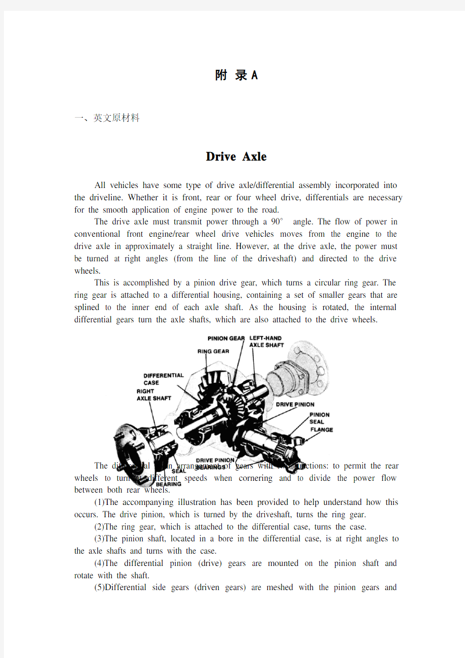
This is accomplished by a pinion drive gear, which turns a circular ring gear. The ring gear is attached to a differential housing, containing a set of smaller gears that are splined to the inner end of each axle shaft. As the housing is rotated, the internal differential gears turn the axle shafts, which are also attached to the drive wheels.
The differential is an arrangement of gears with two functions: to permit the rear wheels to turn at different speeds when cornering and to divide the power flow between both rear wheels.
(1)The accompanying illustration has been provided to help understand how this occurs. The drive pinion, which is turned by the driveshaft, turns the ring gear.
(2)The ring gear, which is attached to the differential case, turns the case.
(3)The pinion shaft, located in a bore in the differential case, is at right angles to the axle shafts and turns with the case.
(4)The differential pinion (drive) gears are mounted on the pinion shaft and rotate with the shaft.
(5)Differential side gears (driven gears) are meshed with the pinion gears and
turn with the differential housing and ring gear as a unit.
(6)The side gears are splined to the inner ends of the axle shafts and rotate the shafts as the housing turns.
(7)When both wheels have equal traction, the pinion gears do not rotate on the pinion shaft, since the input force of the pinion gears is divided equally between the two side gears.
(8)When it is necessary to turn a corner, the differential gearing becomes effective and allows the axle shafts to rotate at different speeds.
As the inner wheel slows down, the side gear splined to the inner wheel axle shaft also slows. The pinion gears act as balancing levers by maintaining equal tooth loads to both gears, while allowing unequal speeds of rotation at the axle shafts. If the vehicle speed remains constant, and the inner wheel slows down to 90 percent of vehicle speed, the outer wheel will speed up to 110 percent. However, because this system is known as an open differential, if one wheel should become stuck (as in mud or snow), all of the engine power can be transferred to only one wheel.
Engineers searched diligently for ways to allow each driving wheel to operate at its own speed. Many ideas were tried with mixed results before the basic design for the present-day, standard differential was finally developed. The successful idea that is still used in principle today was to divide the engine power by dividing the axle in two-attaching each driving wheel separately to its own half-axle and placing in between, an ingenious, free-rotating pinion and gear arrangement. The arrangement was called the differential because it differentiates between the actual speed needs of each wheel and splits the power from the engine into equal driving force to each wheel.
On/off road vehicles and other trucks required to haul heavy loads are sometimes equipped with double reduction axles. A double reduction axle uses two gear sets for greater overall gear reduction and peak torque development. This design is favored for severe-ser-vice applications, such as dump trucks, cement mixers, and
other heavy haulers.
The double reduction axle uses a heavy-duty spiral bevel or hypoid pinion and ring gear combination for the first reduction. The second reduction is accomplished with a wide-faced helical spur pin-ion and gear set. The drive pinion and ring gear function just as in a single reduction axle. However, the differential case is not bolted to the ring gear. Instead, the spur pinion is keyed to and driven by the ring gear. The spur pinion is in turn constantly meshed with the helical spur gear to which the differential case is bolted.
Many heavy duty trucks are equipped with two rear drive axles. These tandem axle trucks require a special gear arrangement to deliver power to both the forward and rearward rear driving axles. This gearing must also be capable of allowing for speed differences between the axles. Two axle hub arrangements are available to provide support between the axle hub and the truck's wheels: the semi-floating type axle and the fully floating type axle. Of the two ,the semi-floating is the simplest, cheapest design to incorporate ,but the fully floating axle is more popular in heavy-duty trucks.
In the semi-floating type axle, drive power from the differential is taken by each axle half-shaft and transferred directly to the wheels. A single bearing assembly, located at the outer end of the axle, is used to support the axle half-shaft. The part of the axle ex-tending beyond the bearing assembly is either splined or tapered to a wheel hub and brake drum assembly. The main disadvantage of this type of axle is that the outer end of each axle shaft must carry and support the weight of the truck that is placed on the wheels. If an axle half-shaft should break ,the truck's wheel will fall off.
Drive axle operation is controlled by the differential carrier assembly. A differential carrier assembly consists of a number of major components. These include:
1. Input shaft and pinion gear
2. Ring gear
3. Differential with two differential case halves, a differential spider ,four pinion gears ,and two side gears with washers.
This differential assembly fits between the axle shafts, with the shafts being splined to the differential side gears. The parts of the differential carrier are held in position by a number of bearings and thrust washers.
The leading end of the input shaft is connected to the drive shaft by a yoke and universal joint. The pinion gear on the other end of the input shaft is in constant mesh with the ring gear. The ring gear is bolted to a flange on the differential case. Insied the case, the legs of the spider are held in matching grooves in the case halves. The legs of the spider also support the four pinion gears. In addition ,the case houses the side gears ,which are in mesh with the pinions and are splined to the axle shafts.
When the drive shaft torque is applied to the input shaft and drive pinion, the input shaft and pinion rotate in a direction that is perpendicular to the truck's drive axles. The drive pinion is beveled at 45 degrees and engages the ring gear, which is also beveled at 45 degrees, causing the ring gear to revolve at 90 degrees to the drive
shaft. This means the torque flow changes direction and becomes parallel to the axles and wheels.
The drive shaft must also be able to change in length while transmitting torque. As the rear axle reacts to road surface changes, torque reactions and braking forces, it tends to rotate for-ward or backward, requiring a corresponding change in the length of the drive shaft. In order to transmit engine torque to the rear axles, the drive shaft must be durable and strong. An engine producing 1 000 pound--feet of torque, when multiplied by a 12 to t gear ration in the transmission, will deliver 12 000 pound-feet breakaway torque to the drive shaft. The shaft must be strong enough to deliver this twisting force to a loaded axle without deforming or cracking under the strain.
Drive shafts are constructed of high-strength steel tubing to provide maximum strength with minimum weight. The diameter of the shaft and wall thickness of the tubing is determined by several factors ~ maximum torque and vehicle payload, type of operation, road conditions, and the brake torque that might be encountered. One-piece ,two-piece ,and three-piece drive shafts are used, depending on the length of the drive line. Each end of the drive shaft has a yoke used to connect the shaft to other drive line components. The yoke might be rigidly welded to the shaft tube or it might be a spline, or slip yoke. The tube yokes are connected through universal joints to end yokes on the output and input shafts of the transmission and axle.
A typical slip joint consists of a hardened, ground splined shaft welded to the drive shaft tube that is inserted into a slip yoke that has matching internal splines. The sliding splines between a slib joint and a permanent joint must support the drive shaft and be capable of sliding under full torque loads. The propeller shaft is generally hollow to promote light weight and of a diameter sufficient to impart great strength. Quality steel, aluminum, and graphite are used in its construction. Some have a rubber mounted torsional damper.
The universal yoke and splined stub (where used) are welded to the ends of a hollow shaft. The shaft must run true, and it must be carefully balanced to avoid vibrations. The propeller shaft is often turning at engine speeds. It can cause great damage if bent, unbalanced or if there is wear in the universal joints. As the rear axle moves up and down, it swings on an arc that is different from that of the drive line. As a result, the distance between transmission and rear axle will change to some extent.
When the propeller shaft turns the differential, the axles and wheels are driven forward. The driving force developed between the tires and the road is first transferred to the rear axle housing. From the axle housing, it is transmitted to the frame or body in one of three ways:
1. Through leaf springs that are bolted to the housing and shackled to the frame.
2. Through control or torque arms shackled to both frame and axle housing.
3. Through a torque tube that surrounds the propeller shaft which is bolted to the axle housing and pivoted to the transmission, by means of a large ball socket.
二、中文翻译
驱动桥
汽车传动系统中驱动桥和差速器有许多形式。无论是前轮、后轮还是四轮驱动,差速器都是必要的,以便使发动机的功率充分的发挥到路面上。
驱动桥必须通过一个90°角传递动力。以传统的后轮驱动汽车为例,动力由前置引擎传到大致在一条直线上的驱动桥,然后动力必须经过一个直角传递给驱动车轮。
这一过程是通过一个小齿轮传递到一个齿圈上而完成的。该齿圈连接到差速器壳,壳里面装有一组小齿轮,小齿轮与带有花键的每个轴的轴端相联接,由桥壳的旋转,从而差速齿轮带动轴转动,这个轴同时连接的就是驱动车轮。
图示为一个典型驱动桥的组成
差速器齿轮具有两个基本的功能:在转弯时允许后轮以不同的速度转动并将动力分配到两后轮。
(1)提供的说明是为了帮助理解这一过程是如何实现的。轴带动小驱动齿轮在齿圈上旋转。
(2)该齿圈与差速器壳相连,并带动壳旋转。
(3)差速器壳内设有一小孔,放置一个小齿轮轴,该小轴与差速器成直角,并随壳体转动。
(4)差速行星齿轮驱动装在小轴上的齿轮,使轴转动。
(5)差速器边上的齿轮(驱动齿轮)与小齿轮啮合,并与做在一体的差速器壳和齿圈一起转动。
(6)一侧带花键的齿轮与两轴端配合,随桥壳旋转。
(7)当两车轮具有相同的驱动力的时候,小齿轮(行星齿轮)在其轴架(行星架)上不旋转,输入到小齿轮上的力平均分配给两端的齿轮。
(8)当需要转弯时,差动齿轮开始起作用,能够实现两端的半轴以不同的速度旋转。
由于内侧车轮速度减慢,同侧的花键轴齿轮也变慢,行星齿轮作为平衡杠杆,保持两边的轮齿负荷相等,同时允许两边的半轴以不同的的速度旋转。如果汽车的行进速度保持不变,内侧车轮的速度将减低90%。外侧车轮的速度将增加到110%。但是,因为系统有差速器,所以一旦有一个车轮转速保持不变(如在泥或雪地),那么所有的发动机功率将全部转移到另外的一个车轮。
工程师们努力地寻找方法使每个驱动轮都按照自己的速度运行。在如今标准的差速器被最终发明出来之前,许多想法被交叉尝试。目前在理论上非常成功的、一直沿用到今天的想法是通过把车轴分离成对称的两部分。每一个半轴都连接到分离的驱动轮上,然后中间安放一个独立的自由旋转的小齿轮和其它两个齿轮来分离来自发动机的动力。这个结构被称为差速装置。因为这种装置能提供给每个车轮实际所需要的速度并且把来自发动机的动力分成相同的驱动力作用给每个车轮。许多卡车有时需要装备双级减速驱动桥来拖拽重物。双级减速驱动桥使用两套减速齿轮来降低速度使转矩达到峰值。这种设计是非常受优待的例如自卸式卡车、混凝土搅拌车和其它重型货车。
双减速车桥采用了重型的螺旋锥齿轮或准双曲面齿轮和环行齿轮配合从而进行第一级减速。第二级减速是通过宽面的螺旋柱形直齿轮及其它齿轮组的配合完成的。主动小齿轮和环行齿轮在单级减速桥上运行,而差速器箱没有被环形齿轮锁死,相反,环形齿轮能将柱形直齿轮键入并驱动,柱形直齿轮就可以依次不断地与差速器箱中的螺旋正齿轮相啮合。
许多重型载货汽车都配备了两个后驱动桥,这种平衡悬架轴的卡车需要一种特殊的齿轮配置方法来解决后驱动桥上的向前与向后的传动。这些齿轮必须要考虑到车轴间的转速差。两个车轴轴毂的排列为轴毂和车轮间提供了有力的支持。在半浮动式轴与全浮动式轴中,半浮动式轴的设计较简单、价格便宜的,而全浮动式轴多受欢迎于重型卡车中。
对于半浮动式轴,来自差速器的动力施加与两个半轴,并直接传递到轮子上。一个单轴承组(位于轴承外端)被用于支撑半轴。轴端外延到轴承组上的部分与轮闸和轮鼓的连接是花键或锥形连接。这种轴的缺点是每个半轴的外端都有支撑轮子上的车体。如果有一个半轴断裂,车轮就会脱离。
驱动轴的动作由差速器结构控制。差速器结构由以下几个主要的部件:
1.输入轴和齿轮结构
2.齿圈
3.差速器包括两个差速器半箱,差速架,4个齿轮,两个带垫圈的边齿轮。
差速器结构位于两个半轴之间,通过边齿轮与之花键连接。差速器部件用许多轴承和止推垫圈固定。
输入轴头通过一个套和万向节与驱动轴连接。输入轴另一端的齿轮与齿圈啮合。齿圈被销在差速箱的轮缘上。箱内,支架腿啮合与箱子的凹槽。支架腿同时支撑着4个小齿轮。此外,差速箱还包裹着边齿轮,而边齿轮与小齿轮啮合并与轴花键连接。当驱动轴的转矩施加与输入轴并带动小齿轮,输入轴和小齿轮就会在与车轴垂直的方向转动。传动齿轮和环形齿轮都通过45°斜齿相互啮合,使环形齿轮与驱动轴的转动方向形成90°角。这意味着扭矩改变了方向后与车轴和车轮平行。
驱动桥在传递转矩的同时还能改变长度。因为后轴反映路面的变化,转矩的反映和制动力的变化,适应向前或者向后的旋转。同时还要适应驱动桥的长度变化。为了把发动机的转矩传递到后轴,驱动桥必须耐用而且结实。发动机产生1000镑·尺的转矩时乘以一个齿轮12个齿在驱动桥上就产生了12000镑·尺的转矩。后轴必须足够结实来传递扭转力矩给承载轴上不能产生变形和段裂。
驱动桥是由高强度的空心钢管制成的以最小的重量来提供最大的动力轴的直径和轴壁的薄厚是由扭矩的峰值、车辆的额定载重、运行的方式、路面状况和制动力矩共同决定的。每一个驱动桥的末端都有十字轴用来连接轴和其它的纵向驱动组件的。这个十字轴被刚性的焊接在半轴的软管上或者是滑动叉上。这个支撑管一头连接着万向节,另一头接在支配管上用来输入和输出变速器和轴的动力。
一个经淬火的滑联合,花键轴焊接传动轴管插入一个滑动叉有内花键相配合。滑动花键之间的滑动联合常设联合必须支持传动轴,并承受滑动下全负荷扭矩。传动轴是空心的,并重量轻普遍应用,一个足够大的直径以传递的巨大转矩。优质钢、铝、石墨被用于制造的材料。并安装一个橡胶的扭振减振阻尼器。
普遍的轭状花键管被焊接到两端的空心轴。轴的运行必须准确,并它必须小心平衡,以避免受振动。传动轴往往是转弯时发动机的转速。如果转弯时,
不平衡或有磨损的万向节,它可以造成很大损害。由于后轴上下移动,它摇摆出一个弧形的,不同的传动线。在变速器和后轴将有某种程度的改变。
当传动轴转差,车轴和车轮是驱动前进。主动力之间的轮胎和道路是首先被转移到后轴壳。从动轴套,它是传送给骨架或机构,其中有3种方式:
1.通过钢板弹簧,螺栓,以及桥壳和骨架的束缚。
2.通过控制或扭力杆两种构架及轴壳的束缚。
3.通过扭力杆,环绕在传动轴的螺栓与轴壳的传输,采用了大的球形支座。
汽车专业毕业设计外文翻译
On the vehicle sideslip angle estimation through neural networks: Numerical and experimental results. S. Melzi,E. Sabbioni Mechanical Systems and Signal Processing 25 (2011):14~28 电脑估计车辆侧滑角的数值和实验结果 S.梅尔兹,E.赛博毕宁 机械系统和信号处理2011年第25期:14~28
摘要 将稳定控制系统应用于差动制动内/外轮胎是现在对客车车辆的标准(电子稳定系统ESP、直接偏航力矩控制DYC)。这些系统假设将两个偏航率(通常是衡量板)和侧滑角作为控制变量。不幸的是后者的具体数值只有通过非常昂贵却不适合用于普通车辆的设备才可以实现直接被测量,因此只能估计其数值。几个州的观察家最终将适应参数的参考车辆模型作为开发的目的。然而侧滑角的估计还是一个悬而未决的问题。为了避免有关参考模型参数识别/适应的问题,本文提出了分层神经网络方法估算侧滑角。横向加速度、偏航角速率、速度和引导角,都可以作为普通传感器的输入值。人脑中的神经网络的设计和定义的策略构成训练集通过数值模拟与七分布式光纤传感器的车辆模型都已经获得了。在各种路面上神经网络性能和稳定已经通过处理实验数据获得和相应的车辆和提到几个处理演习(一步引导、电源、双车道变化等)得以证实。结果通常显示估计和测量的侧滑角之间有良好的一致性。 1 介绍 稳定控制系统可以防止车辆的旋转和漂移。实际上,在轮胎和道路之间的物理极限的附着力下驾驶汽车是一个极其困难的任务。通常大部分司机不能处理这种情况和失去控制的车辆。最近,为了提高车辆安全,稳定控制系统(ESP[1,2]; DYC[3,4])介绍了通过将差动制动/驱动扭矩应用到内/外轮胎来试图控制偏航力矩的方法。 横摆力矩控制系统(DYC)是基于偏航角速率反馈进行控制的。在这种情况下,控制系统使车辆处于由司机转向输入和车辆速度控制的期望的偏航率[3,4]。然而为了确保稳定,防止特别是在低摩擦路面上的车辆侧滑角变得太大是必要的[1,2]。事实上由于非线性回旋力和轮胎滑移角之间的关系,转向角的变化几乎不改变偏航力矩。因此两个偏航率和侧滑角的实现需要一个有效的稳定控制系统[1,2]。不幸的是,能直接测量的侧滑角只能用特殊设备(光学传感器或GPS惯性传感器的组合),现在这种设备非常昂贵,不适合在普通汽车上实现。因此, 必须在实时测量的基础上进行侧滑角估计,具体是测量横向/纵向加速度、角速度、引导角度和车轮角速度来估计车辆速度。 在主要是基于状态观测器/卡尔曼滤波器(5、6)的文学资料里, 提出了几个侧滑角估计策略。因为国家观察员都基于一个参考车辆模型,他们只有准确已知模型参数的情况下,才可以提供一个令人满意的估计。根据这种观点,轮胎特性尤其关键取决于附着条件、温度、磨损等特点。 轮胎转弯刚度的提出就是为了克服这些困难,适应观察员能够提供一个同步估计的侧滑角和附着条件[7,8]。这种方法的弊端是一个更复杂的布局的估计量导致需要很高的计算工作量。 另一种方法可由代表神经网络由于其承受能力模型非线性系统,这样不需要一个参
驱动桥外文翻译
驱动桥设计 随着汽车对安全、节能、环保的不断重视,汽车后桥作为整车的一个关键部件,其产品的质量对整车的安全使用及整车性能的影响是非常大的,因而对汽车后桥进行有效的优化设计计算是非常必要的。 驱动桥处于动力传动系的末端,其基本功能是增大由传动轴或变速器传来的转矩,并将动力合理地分配给左、右驱动轮,另外还承受作用于路面和车架或车身之间的垂直力力和横向力。驱动桥一般由主减速器、差速器、车轮传动装置和驱动桥壳等组成。 驱动桥作为汽车四大总成之一,它的性能的好坏直接影响整车性能,而对于载重汽车显得尤为重要。驱动桥设计应当满足如下基本要求: 1、符合现代汽车设计的一般理论。 2、外形尺寸要小,保证有必要的离地间隙。 3、合适的主减速比,以保证汽车的动力性和燃料经济性。 4、在各种转速和载荷下具有高的传动效率。 5、在保证足够的强度、刚度条件下,力求质量小,结构简单,加工工艺性 好,制造容易,拆装,调整方便。 6、与悬架导向机构运动协调,对于转向驱动桥,还应与转向机构运动协调。智能电子技术在汽车上得以推广使得汽车在安全行驶和其它功能更上一层楼。通过各种传感器实现自动驾驶。除些之外智能汽车装备有多种传感器能充分感知交通设施及环境的信息并能随时判断车辆及驾驶员是否处于危险之中,具备自主寻路、导航、避撞、不停车收费等功能。有效提高运输过程中的安全,减少驾驶员的操纵疲劳度,提高乘客的舒适度。当然蓄电池是电动汽车的关键,电动汽车用的蓄电池主要有:铅酸蓄电池、镍镉蓄电池、钠硫蓄电池、钠硫蓄电池、锂电池、锌—空气电池、飞轮电池、燃料电池和太阳能电池等。在诸多种电池中,燃料电池是迄今为止最有希望解决汽车能源短缺问题的动力源。燃料电池具有高效无污染的特性,不同于其他蓄电池,其不需要充电,只要外部不断地供给燃料,就能连续稳定地发电。燃料电池汽车(FCEV)具有可与内燃机汽车媲美的动力性能,在排放、燃油经济性方面明显优于内燃机车辆。
外文文献翻译:汽车的发展
The development of automobile As the world energy crisis and the war and the energy consumption of oil -- and are full of energy in one day someday it will disappear without a trace. Oil is not inresources. So in oil consumption must be clean before finding a replacement. With the development of science and technology the progress of the society people invented the electric car. Electric cars will become the most ideal of transportation. In the development of world each aspect is fruitful especially with the automobile electronic technology and computer and rapid development of the information age. The electronic control technology in the car on a wide range of applications the application of the electronic device cars and electronic technology not only to improve and enhance the quality and the traditional automobile electrical performance but also improve the automobile fuel economy performance reliability and emission spurification. Widely used in automobile electronic products not only reduces the cost and reduce the complexity of the maintenance. From the fuel injection engine ignition devices air control and emission control and fault diagnosis to the body auxiliary devices are generally used in electronic control technology auto development mainly electromechanical integration. Widely used in automotive electronic control ignition system mainly electronic control fuel injection system electronic control ignition system electronic control automatic transmission electronic control ABS/ASR control system electronic control suspension system electronic control power steering system vehicle dynamic control system the airbag systems active belt system electronic control system and the automatic air-conditioning and GPS navigation system etc. With the system response the use function of quick car high reliability guarantees of engine power and reduce fuel consumption and emission regulations meet standards. The car is essential to modern traffic tools. And electric cars bring us infinite joy will give us the physical and mental relaxation. Take for example automatic transmission in road can not on the clutch can achieve automatic shift and engine flameout not so effective improve the driving convenience lighten the fatigue strength. Automatic transmission consists mainly of hydraulic torque converter gear transmission pump hydraulic control system electronic control system and oil cooling system etc. The electronic control of suspension is mainly used to cushion the impact of the body and the road to reduce vibration that car getting smooth-going and stability. When the vehicle in the car when the road uneven road can according to automatically adjust the height. When the car ratio of height low set to gas or oil cylinder filling or oil. If is opposite gas or diarrhea. To ensure and improve the level of driving cars driving stability. Variable force power steering system can significantly change the driver for the work efficiency and the state so widely used in electric cars. VDC to vehicle performance has important function it can according to the need of active braking to change the wheels of the car car motions of state and optimum control performance and increased automobile adhesion controlling and stability. Besides these appear beyond 4WS 4WD electric cars can greatly improve the performance of the value and ascending simultaneously. ABS braking distance is reduced and can keep turning skills effectively improve the stability of the directions simultaneously reduce tyre wear. The airbag appear in large programs protected the driver and passengers safety and greatly reduce automobile in collision of drivers and passengers in the buffer to protect the safety of life. Intelligent electronic technology in the bus to promote safe driving and that the other functions. The realization of automatic driving through various sensors. Except some smart cars equipped with multiple outside sensors can fully perception of information and traffic facilities
汽车设计课设驱动桥设计
汽车设计课程设计说明书 题目:BJ130驱动桥部分设计验算与校核 姓名: 学号: 专业名称:车辆工程 指导教师: 目录 一、课程设计任务书 (1) 二、总体结构设计 (2) 三、主减速器部分设计 (2) 1、主减速器齿轮计算载荷的确定 (2) 2、锥齿轮主要参数选择 (4) 3、主减速器强度计算 (5) 四、差速器部分设计 (6) 1、差速器主参数选择 (6) 2、差速器齿轮强度计算 (7) 五、半轴部分设计 (8) 1、半轴计算转矩Tφ及杆部直径 (8) 2、受最大牵引力时强度计算 (9) 3、制动时强度计算 (9) 4、半轴花键计算 (9) 六、驱动桥壳设计 (10) 1、桥壳的静弯曲应力计算 (10) 2、在不平路面冲击载荷作用下的桥壳强度计算 (11) 3、汽车以最大牵引力行驶时的桥壳强度计算 (11) 4、汽车紧急制动时的桥壳强度计算 (12)
5、汽车受最大侧向力时的桥壳强度计算 (12) 七、参考书目 (14) 八、课程设计感想 (15)
一、课程设计任务书 1、题目 《BJ130驱动桥部分设计验算与校核》 2、设计内容及要求 (1)主减速器部分包括:主减速器齿轮的受载情况;锥齿轮主要参数选择;主减速器强度计算;齿轮的弯曲强度、接触强度计算。 (2)差速器:齿轮的主要参数;差速器齿轮强度的校核;行星齿轮齿数和半轴齿轮齿数的确定。 (3)半轴部分强度计算:当受最大牵引力时的强度;制动时强度计算。 (4)驱动桥强度计算:①桥壳的静弯曲应力 ②不平路载下的桥壳强度 ③最大牵引力时的桥壳强度 ④紧急制动时的桥壳强度 ⑤最大侧向力时的桥壳强度 3、主要技术参数 轴距L=2800mm 轴荷分配:满载时前后轴载1340/2735(kg) 发动机最大功率:80ps n:3800-4000n/min 发动机最大转矩17.5kg﹒m n:2200-2500n/min 传动比:i1=7.00; i0=5.833 轮毂总成和制动器总成的总重:g k=274kg
驱动桥5000字外文翻译文献
As the bearing cage rotates, read the value 7. indicated on the scale. Preload normally is specified as torque re-8. quired to rotate the pinion bearing cage, so take a reading only when the cage is rotating. Starting torque will give a false reading. To calculate the preload torque, measure the 9. diameter of the bearing cage where the cord was wound. Divide this dimension in half to get the radius. 10. U se the following procedure to calculate the bearing preload torque:Standard. Pull (lb) 3 radius (inches) 5 preload (lb-in.)or Preload (lb-in.) 3 0.113 (a conversion constant) 5 preload (N .m) Install the yoke, flat washer, and nut. Tighten 6. the nut snugly. Tap the end of the input shaft lightly to seat the bearings. Measure the input shaft endplay again with 7. the dial indicator. If endplay is still incorrect, repeat steps 3 through 7. With the endplay correct, seal the shim pack 8. to prevent lube leakage. Then torque the i nput shaft nut and cover capscrews to the correct value. 24.5 A XLE ADJUSTMENTS AND CHECKS This section introduces the differential carrier adjust-ments, checks, and tests that the truck technician must be capable of performing; some have been r eferred to previously in the text. For the most part, the procedures described here are general in nature. The truck technician should refer to OEM service l iterature for specific procedures.PINION BEARING PRELOAD Most differential carriers are provided with a press-fit outer bearing on the drive pinion gear. Some older rear drive axles use an outer bearing, which slips over the drive pinion. The procedures for adjusting both types follow. Press-Fit Method Adjustment To adjust the pinion bearing preload using the press-fit method, use the following procedure: Assemble the pinion bearing cage, bearings, 1. spacer, and spacer washer (without drive pin-ion or oil seal). Center the bearing spacer and spacer washer between the two bearing cones (Figure 24–49). When a new gear set or pinion bearings are 2. used, select a nominal size spacer based on OEM specifications. If original parts are used, use a spacer removed during disassembly of the drive. Place the drive pinion and cage assembly in a 3. press, with the gear teeth toward the bottom.Apply and hold the press load to the pinion 4. bearing. As pressure is applied, rotate the bearing cage several times so that the bear-ings make normal contact. While pressure is held against the assembly, wind 5. a cord around the bearing cage several times.Attach a spring scale to the end of the cord 6. (Figure 24–50). Pull the cord with the scale on a horizontal line. FIGURE 24–49 Assembly of the pinion bearing cage. (Courtesy of Dana Corporation) FIGURE 24–50 Cage in press to check bearing p reload. Sleeve must apply
汽车车辆类驱动桥的设计外文文献翻译、外文翻译、中英文翻译
附录I Drive axle powertrain at the end of their basic function is to increase the transmission came from the drive shaft or torque, and a reasonable distribution of power to the left and right wheel, in addition to acting on the road and under the frame or body legislation between the vertical, longitudinal and lateral force. General from the main drive axle reducer, differential, gear wheels and drive axle housings and other components. The design of the Drive axle: Drive axle should be designed to meet the basic requirements are as follows: 1. Select the main reduction ratio should be able to ensure the car has the best power and fuel economy. 2. Smaller size, to ensure that the necessary ground clearance. 3. Gear and other pieces of the work of a smooth transmission,and small noise. 4. In a variety of speed and load with a high transmission efficiency. 5. In ensuring adequate strength and stiffness conditions, should strive for the quality of small, especially under the mass-spring should be as small as possible in order to improve vehicle ride comfort. 6. And suspension movement-oriented coordination of steering drive axle, but also with the coordination of steering movement. 7. The structure of simple, good processing, manufacturing, easy disassembly, to facilitate adjustment. Drive axle classification -1-
汽车保险中英文对照外文翻译文献
汽车保险中英文对照外文翻译文献(文档含英文原文和中文翻译)
汽车保险 汽车保险是在事故后保证自己的财产安全合同。尽管联邦法律没有强制要求,但是在大多数州(新罕布什和威斯康星州除外)都要求必须购买汽车保险;在各个州都有最低的保险要求。在鼻腔只购买汽车保险的两个州,如果没有足够的证据表明车主财力满足财务责任法的要求,那么他就必须买一份汽车保险。就算没有法律规定,买一份合适的汽车保险对司机避免惹上官和承担过多维修费用来说都是非常实用的。 依据美国保险咨询中心的资料显示,一份基本的保险单应由6个险种组成。这其中有些是有州法律规定,有些是可以选择的,具体如下: 1.身体伤害责任险 2.财产损失责任险 3.医疗险或个人伤害保护险 4.车辆碰撞险 5.综合损失险 6.无保险驾驶人或保额不足驾驶人险 责任保险 责任险的投保险额一般用三个数字表示。不如,你的保险经纪人说你的保险单责任限额是20/40/10,这就代表每个人的人身伤害责任险赔偿限额是2万美元,每起事故的热身上海责任险赔偿限额是4万美元,每起事故的财产损失责任险的赔偿限额是1万美元。 人身伤害和财产损失责任险是大多数汽车保险单的基础。要求汽车保险的每个州都强令必须投保财产损失责任险,佛罗里达是唯一要求汽车保险但不要求投保人身伤害责任险的州。如果由于你的过错造成了事故,你的责任险会承担人身伤害、财产损失和法律规定的其他费用。人身伤害责任险将赔偿医疗费和误工工资;财产损失责任险将支付车辆的维修及零件更换费用。财产损失责任险通常承担对其他车辆的维修费用,但是也可以对你的车撞坏的灯杆、护栏、建筑物等其他物品的损坏进行赔偿。另一方当事人也可以决定起诉你赔偿精神损失。
驱动桥设计_毕业设计论文
驱动桥设计 摘要 现代工程车辆技术追求高效节能、高舒适性和高安全性等目标。前一项目标与环境保护密切相关,是当代全球性热门话题,后两项目标是车辆朝着高性能化方向发展必须研究和解决的重要课题。转向系统的高性能化是指其能够根据车辆的运行状况和驾驶员的要求实行多目标控制,以获得良好的转向轻便性、较好的路感和较快的响应性。 汽车转向系统是影响汽车操纵稳定性、行驶安全性和驾驶舒适性的关键部分。在追求高效节能\高舒适性和高安全性的今天,电控液压助力转向系统作为一种新的汽车动力转向系统,以其节能、环保、更佳的操纵特性和转向路感,成为动力转向技术研究的焦点。 本文通过查阅相关的文献,介绍了EHPS系统的结构组成和工作原理,在参考现有车型的结构数据的基础上,设计计算转向系的主要参数,确定转向器的结构参数和动力转向部分结构参数,在分析其助力特性的基础上,设计合理的助力特性曲线,并通过MATLAB作出助力特性图,同时提出一种基于车速和转向盘转动角速度的控制策略,根据EHPS系统的特点,通过AMESim和Simulink建立整个系统的模型。通过联合仿真可以得出EHPS系统比HPS系统能提供更好的助力特性和转向路感。 关键词:EHPS;助力特性;结构设计;AMESim与Simulink建模 ABSTRACT
High effective energy saving,high comfort performance and high security are thegoals of contemporary.The first goal closely concerns with environment protecting,is also the popular topic around the world.The last two goals are the important subjects must be researched and solved in making automobile high performance.To make the steering system high performance is that the system can carry out mufti-goals control according to the vehicle states and drive requirements to acquire the steering handiness,better road feeling,better anti-interfering performance and faster response. The motor turing system is the essential part which affects the automobile operation stability,the travel security and the driving comfortablet.Nowadays we pursue highly effective energy conservation,the high comforrtableness and high secure.The electrically hydraulic power steering (EHPS) taking as one kind of new automobile power steering system,it takes the power steering engineering research the focal point by its energy conservation,the environmental protection,the better handling characteristic and changes the road feeling. According to consult relevant literature, this paper introduces the structure and the principle of EHPS, bases the further study of EHPS on the structural parameter date of a certain type of the light lorry, calculates the main parameters of steering system and power steering and devises the hydraulic circuit of EHPS. On the basis of the analysis of EHPS, this paper designs a reasonable EHPS power curve, including plotting the curve with the technique of MATLAB. Taking into account the steady steering and emergency steering, it advances the control strategy plan based on speed, steering wheel angle velocity, the steering wheel torque. Based on the structural characteristics of EHPS, this paper proposed AMESIM and SIMULINK joint simulation of the entire EHPS system. Accord to the result we can know that EHPS can offer more secure handle, more saving energy and way feeling. Key words:EHPS;Characteristics of power; Structure design; AMESim and Simulink Modeling
驱动桥设计外文翻译
驱动桥设计外文翻译 驱动桥设计 随着汽车对安全、节能、环保的不断重视,汽车后桥作为整车的一个关键部件,其产品的质量对整车的安全使用及整车性能的影响是非常大的,因而对汽车后桥进行有效的优化设计计算是非常必要的。 驱动桥处于动力传动系的末端,其基本功能是增大由传动轴或变速器传来的转矩,并将动力合理地分配给左、右驱动轮,另外还承受作用于路面和车架或车身之间的垂直力力和横向力。驱动桥一般由主减速器、差速器、车轮传动装置和驱动桥壳等组成。 驱动桥作为汽车四大总成之一,它的性能的好坏直接影响整车性能,而对于载重汽车显得尤为重要。驱动桥设计应当满足如下基本要求: 1、符合现代汽车设计的一般理论。 2、外形尺寸要小,保证有必要的离地间隙。 3、合适的主减速比,以保证汽车的动力性和燃料经济性。 4、在各种转速和载荷下具有高的传动效率。 5、在保证足够的强度、刚度条件下,力求质量小,结构简单,加工工艺性 好,制造容易,拆装,调整方便。 6、与悬架导向机构运动协调,对于转向驱动桥,还应与转向机构运动协调。智能电子技术在汽车上得以推广使得汽车在安全行驶和其它功能更上一层楼。通过各种传感器实现自动驾驶。除些之外智能汽车装备有多种传感器能充分感知交通设施及环境的信息并能随时判断车辆及驾驶员是否处于危险之中,具备自主寻路、导航、避撞、不停车收费等功能。有效提高运输过程中的安全,减少驾驶员的操纵疲劳度,提高乘客的舒适度。当然蓄电池是电动汽车的关键,电动汽车用的蓄电池主
要有:铅酸蓄电池、镍镉蓄电池、钠硫蓄电池、钠硫蓄电池、锂电池、锌—空气电池、飞轮电池、燃料电池和太阳能电池等。在诸多种电池中,燃料电池是迄今为止最有希望解决汽车能源短缺问题的动力源。燃料电池具有高效无污染的特性,不同于其他蓄电池,其不需要充电,只要外部不断地供给燃料,就能连续稳定地发电。燃料电池汽车(FCEV)具有可与内燃机汽车媲美的动力性能,在排放、燃油经济性方面明显优于内燃机车辆。 这项发明通常涉及到多能源动力总成的车辆,以及,尤其是多能源动力总成,有多个电源包括电动马达来驱动的汽车轮子。混合动力电动动力系统已经被发展成为包括电机(IC)做内燃机引擎,自主经营的或者联合根据行驶条件下,国家费用的牵引电池,与电源,最有效地满足当前所产生的电力需求车辆操作。大部分电子混合动力汽车可以在市场上买到是前轮驱动车辆,只不过前轮带动起来的。混合动力电动动力系统被开发用于四轮驱动车,允许两个电机和引擎传送权力后方的驱动轮。当包装电动马达驱动后桥机组是较好的使用躺轴功率流,马达驱动单元被放在后桥中心线。这样的电的混合动力系统,然而,现在的包装设计很困难,特别是当副轴车辆传动是用来传输动力,纵向驱动轴后轴。需要混合动力电动存在的动力,在其中轴是靠电动机驱动的或的内燃机结合电机。以减少成本,电动机器将提供所有混合功能,包括电气能源的产生、电动汽车、电子发动机启动投放 提高发动机的功率,再生式制动。一个驱动器单位是混合动力电动汽车包括市场, 发动机,电动机器包括转子,副轴,齿轮组包括一个输入可驱动的连接到发动机和输出,用来传送之间权限投入与产出和生产第一速度微分导致一个录入速度超过每小时的速度输出,第一和第二驾车轴差动机构可驱动的连接到输出线时,因为传输功率和输出之间驾车轴,可驱动的行星齿轮装置连接到输出和转子,说之间权限传输转子和输出线,制作了第二速度微分导致转子速度超过速度输出。转矩反应为减速
机械毕业设计英文外文翻译399驱动桥
附录A 英文文献 Drive Axle All vehicles have some type of drive axle/differential assembly incorporated into the driveline. Whether it is front, rear or four wheel drive, differentials are necessary for the smooth application of engine power to the road. Powerflow The drive axle must transmit power through a 90°angle. The flow of power in conventional front engine/rear wheel drive vehicles moves from the engine to the drive axle in approximately a straight line. However, at the drive axle, the power must be turned at right angles (from the line of the driveshaft) and directed to the drive wheels. This is accomplished by a pinion drive gear, which turns a circular ring gear. The ring gear is attached to a differential housing, containing a set of smaller gears that are splined to the inner end of each axle shaft. As the housing is rotated, the internal differential gears turn the axle shafts, which are also attached to the drive wheels. Rear-wheel drive Rear-wheel-drive vehicles are mostly trucks, very large sedans and many sports car and coupe models. The typical rear wheel drive vehicle uses a front mounted engine and transmission assemblies with a driveshaft coupling the transmission to the rear drive axle. Drive in through the layout of the bridge, the bridge drive shaft arranged vertically in the same vertical plane, and not the drive axle shaft, respectively, in their own sub-actuator with a direct connection, but the actuator is located at the front or the back of the adjacent shaft
汽车变速器设计外文翻译
汽车变速器设计 ----------外文翻译 我们知道,汽车发动机在一定的转速下能够达到最好的状态,此时发出的功率比较大,燃油经济性也比较好。因此,我们希望发动机总是在最好的状态下工作。但是,汽车在使用的时候需要有不同的速度,这样就产生了矛盾。这个矛盾要通过变速器来解决。 汽车变速器的作用用一句话概括,就叫做变速变扭,即增速减扭或减速增扭。为什么减速可以增扭,而增速又要减扭呢?设发动机输出的功率不变,功率可以表示为 N = w T,其中w是转动的角速度,T是扭距。当N固定的时候,w与T是成反比的。所以增速必减扭,减速必增扭。汽车变速器齿轮传动就根据变速变扭的原理,分成各个档位对应不同的传动比,以适应不同的运行状况。 一般的手动变速器内设置输入轴、中间轴和输出轴,又称三轴式,另外还有倒档轴。三轴式是变速器的主体结构,输入轴的转速也就是发动机的转速,输出轴转速则是中间轴与输出轴之间不同齿轮啮合所产生的转速。不同的齿轮啮合就有不同的传动比,也就有了不同的转速。例如郑州日产ZN6481W2G型SUV车手动变速器,它的传动比分别是:1档3.704:1;2档2.202:1;3档1.414:1;4档1:1;5档(超速档)0.802:1。 当汽车启动司机选择1档时,拨叉将1/2档同步器向后接合1档齿轮并将它锁定输出轴上,动力经输入轴、中间轴和输出轴上的1档齿轮,1档齿轮带动输出轴,输出轴将动力传递到传动轴上(红色箭头)。典型1档变速齿轮传动比是3:1,也就是说输入轴转3圈,输出轴转1圈。 当汽车增速司机选择2档时,拨叉将1/2档同步器与1档分离后接合2档齿轮并锁定输出轴上,动力传递路线相似,所不同的是输出轴上的1档齿轮换成2档齿轮带动输出轴。典型2档变速齿轮传动比是2.2:1,输入轴转2.2圈,输出轴转1圈,比1档转速增加,扭矩降低。